My garage is no longer a black hole. In outer space, a black hole brings back light with a long series of uncomfortable side effects. Overheating, explosions, and there is no way you can control what direction you are going when the dark turns to light. My garage lights up when it sees the brake lights on my car, and guide me to the same spot every time. My garage can even communicate over Bluetooth.
Luckily, my wife can almost never be blamed for any of our car incidents. If she were to cause some trouble, I would probably stigmatize her and blame her for being a typical woman. I would say she is stressed out over normal traffic and putting on makeup in the rear view mirror while driving. She would feel very bad, and probably try to camouflage the dents with mascara or whatever black she has in her purse.
She makes a mess inside the car, though. She believes the car is an extension of her purse, and throws bags, receipts and extra pairs of shoes everywhere. But that can easily be cleaned out.
I run into poles in parking lots and my own garage.
And this is where the AVR is coming to my rescue: I’m making a device that turns on the lights in the garage for me when it sees my brake lights, backing in.
When it is rainy and dark (the average weather in Bergen) the rearview mirrors cover with rain drops, dispersing my visual rays into a blur. The garage opening is a narrow black hole. You might think that this black hole has so high gravity that it sucks the car in, but no, the only mass in there is a set of spare wheels and years of dust.
I think the garage was built sometime in the medieval, when people were tiny and families didn’t travel much. I might be wrong about history, but the garage is small. Leaving little space on either side or in front of the car when it is parked and the gate is closed. So I need light to see. Automatic lights.
I could of course switch on the lights when I’m out opening the gate, but that would be a change of routine. And the brain is rigged to celebrate lazy repetitiveness in the daily operations, and punish any attempt on changing. Try brushing your teeth with the hand that normally just hangs around while teeth get their daily shampoo, and you will feel the backlash from the hub. I might be able to turn on the garage light every time I open the gate, but I might also end up forgetting to put on pants or bring the kids. Not something I’m willing to risk, so I make something new and slightly useful to do the job.
The brain loves creativity. Learning new habits takes rounds and rounds of repetition
You got the concept? I back up to the garage, a light sensor sees my brake lights, and turns on LED strips in the garage to illuminate my path of easy parking. No more expensive and embarrassing repairs on the car or the garage.
Of course there will be an AVR controlling the lights, and I will use a Light Dependent Resistor (LDR) to see the brake lights. The PCB layout will be similar to my shelf light project, but this time I will use the Analog to Digital Converter (ADC) in the AVR. The ADC turns the resistance readings from the LDR into a number, and I can set a threshold for when to turn on and off the LED strips (which I will mount in the garage. Also, I will add a serial connection with a bluetooth device to help me calibrate the sensor, and perhaps add more features later on. It will run of grid power with a 12V DC converter in the socket.
Based on the Montana shelves available in high-class furniture stores, I have built a shelf and a book-case where my AVR project controls the lights. Here is how I did the woodwork for the book-case.
Working on the book-case. Oil paint give strong and lasting colors
The design of shelf and book-case is based on the height of the table, to frame the table as a play place, and to provide light for art work, alphabet training, and general mess-making. The table and chairs were bought online in the US, and is very nice woodwork done by the Amish people.
The Montana shelves are made of MDF, a material I have some experience from when I built speakers some years ago. MDF is very easy to work with, it is soft like butter when I use the router to carve out shapes and corners, and the surface is slick. The downside with MDF is that it is rather heavy, and not very strong, so long cut outs tend to bend and deform. Also, it soaks up water, damaging the surface, and makes a serious mess when it is carved in (dust everywhere). For my project I decided to go with plywood, and use the Montana design as inspiration.
Book case schematic from SketchUp
I made a Sketchup of the design before starting the woodwork. Sketchup is a very good tool for quick prototyping, sharing of concepts, and detail 3D drawing of a project. When I first starting to use the software, I installed the free and easy-to-use software, followed some tutorials and looked on YouTube for more details, and it didn’t take me more than a couple of hours to be able to make decent 3D drawings on my own with Sketchup. Now I use Sketchup as often as I can, as it’s quite fun to use.
When I built the shelf, I made some simple length and width measurements and started cutting.
Lessons learnt
I had a few experiences from making the shelf above the table that I wanted to implement in the design and manufacturing of the book shelf:
Use a better saw to get cleaner and straighter cuts
Sand, sand, sand and sand the surface of the plywood
Route out grooves for the insert shelf dividers for a snug and smooth fit
Make sure everything fits and lines up well before gluing (save some sanding)
Fill all holes and mistakes with wood filler and sand well
Design and manufacturing
The outer frame of the book-case is cut out from one sheet of 12mm birch plywood, with plenty plywood remaining from the 2.4 by 1.2m sheet. The corners are all cut with 45 degree angles, to create smooth and simple-to-mount design. Before gluing together, I used the router with a 9mm bit to make grooves where the dividing floors fits in.
To cut the surfaces I used a table saw, which provides very precise measuring of width and length, and a clean cut. I got a list of parts from Sketchup, and drew them up on the plywood sheet, and started cutting. With the table saw it was done very quickly, I think it was all done in about an hour. Also the 45 degree ends were cut with the table saw.
The finish of the shelf I made before was only decent, so this time I put more effort into sanding and improving the surface. After cutting the 12mm plywood into boards for sides and tops of the book-case, I sanded the sides down. I used coarse (120), medium (150) and fine (240) sandpaper to smooth out the wooden structure of the plywood, and filled in all dents or damages to the wooden structure with wood filler. The wood filler was applied in several coatings, sanding it down after letting the filler dry.
I cut the dividing shelves out from a sheet of 9mm plywood. The are as wide as the depth of the book-case, plus two times 6mm (i’ll explain why). On both the short ends, a 6mm x 2 cm piece was removed on both sides.
The reason why I added 6mm on both sides of the dividing shelves, was to engrave them in the side walls for a snug and professional look. I used a 6mm bit on my new Makita RP0900 router (thank you wife for birthday present), and ran it twice, with a 3mm offset the second run, to make 9mm grooves in the side walls. In the grooves, the dividing shelves fit tightly. I stopped the grooves 2cm from the edge, to avoid visible grooves (matching the cutouts on the dividing shelves corners).
Pink and red make the design stand out
The frame was glued in one go, using regular wood glue. I applied generous amounts of glue to the dividers and the corners of the frame, and clamped everything together with large clamps.
After gluing the book-case together, with the dividers glued in place in the routed out grooves, I used the router to cut round edges. I used a rounding bit, and hand-held the router as I walked it around all surfaces and corners. Remember to push the router in the direction where the bit digs into the wood, not scrapes out (look for the arrow indicating the direction of rotation on the router).
Play table with new builds
Then I sanded down the routed edges, where the five layers of the 12mm plywood is visible. The layers of plywood have mixed quality and structure direction to create strength and low-cost, so the ends are hard to make really slick and smooth with sand paper. To create a nice finish, I covered the edges with thin layer of wood filler, let dry, and sanded down. The result was a very clean and smooth finish, much better than with the top shelf, where I just sanded the frame.
The shelf dividers were painted in pink, and the frame in dark red with oil based paint. I picked the colors for the top shelf by going to the hardware store with my daughter, and let her pick her favorite colors from all the color samples. With the two color, slick and clean design, the result looks modern and useful.
My wife congratulated me on the build with comforting words: “Much better than most of the stuff I have made before”. Then she approved it for the living room. For now.
Electron paths
The AVR control with switch and indicator lights (wiring to be improved)
The AVR for light control is protected under a 5mm sheet of extruded PVC I bought from a local sign maker. Not that there are any dangerous to touch components, but to improve the lifetime of the light controls, I wanted a protection plate. Also the flexible PVC sheet doubles as button, a nylon screw pushes down on the PCB mounted tactile switch with a gentle push. Clicks on the button turn on, dim, and turn off the lights, as shown in the code for the AVR.
I drilled holes in the PVC sheet for the status lights, and used nylon spacers to mount the PVC panel to the PCB. I got the spacers from ebay, and they are a good substitute to steel screws and spacers with light weight, matte surface, and non-conductive material.
Lights are installed in the shelf, below the shelf, and in the upper section of the book-case. I have made a hole in the wall of the shelf where the wires for the in-shelf lighting comes out. The wires from the top section of the book-case joins with the wires from the in-shelf light with a t-intersection i soldered.
2.54mm (0.1in) spaced headers were used as connectors for the light wires going into the PCB.
Power is drawn from a 12V 1.5A 240V power adapter, which runs along the shelf and into a PCB mounted 5mm power jack.
I have made a socket for the bookcase to align in height with the top shelf, and I used furniture corners to mount the two wood structures together with screws in the top.
All in all this has been a very fun project, as well as cheap, educating, and I recommend you do this yourself, and post comments below on how you progress.
When making a project with an AVR chip like the Atmega 168, the chip will be moved from the burning station to the project PCB many times, and my setup with burning on a breadboard, and installing in a dock on the PCB. Now I need a smarter way to burn the AVR with new updates, which does not require a screw driver and bending on the Atmega to get it re-made.
ZIF and LED on PCB
A Zero Insert Force (ZIF) socket is a good solution to the challenge, as it is easy to mount, and easy to use. It is a little larger than just a socket, but it is (I hope) a lasting device, that can be used over and over again.
On the Arduino, there is an ICSP pin section with six pins, for power, ground, communication and reset. These pins are used to program the Atmega 328 on the Arduino, so the. All the pins can be used for burning an external Atmega, except for the reset pin. The reset pin resets the 328 on the Arduino, and is used as part of the programming of the 328, not for burning an external AVR. Hence a single cable to pin 10 on the Arduino is necessary.
A later add-on is to install headers on the side of the ZIF, and solder these to the pins on the ZIF. That would make me the owner of a ZIFuino.
Soldering connector
The ZIF is placed on a PCB so that it has equal space on each side. The pins on the ZIF are soldered to the PCB one by one, and I later connect wires on the backside of the PCB. Note that the pins don’t go all the way up to the top of the green box, where the lock and release handle is positioned. Next to the lock and release handle of the ZIF is the 6 pin connector. I used two three-pin headers, inserted them into the connector, so the headers were held in place while I soldered the headers to the the PCB. Another good way to solder headers is to set the headers in a breadboard, and then lay the PCB over, and solder. That didn’t work in this project, as the ZIF socket is taller than the headers.
6 pin connector cable
I made a cable package with six cables, connected to a six pin connector in each end. I soldered all six cables in one end. In the other I left the reset cable out, and soldered on a single wire, to be connected to pin 10 on the Arduino. After soldering I added some heat shrink tube to protect the cables.
Unfortunately, I forgot a resistor for the LED, so the lamp burnt out with a blink when I powered up. The 5V input, running through the 1.7V LED gave too much current flowing through. I resolder the LED and add a 220 ohm resistor.
ZIF programmer
Back at the computer desk, I plugged the 6 pin connector to the Arduino ISCP and the free wire to pin 10, and inserted the connector on the PCB, and voila, no more screwdrivers and tongs to get the Atmega out of the mill.
Much code ends up on the shelf for a later project. My project is making a shelf with lights coming out of a couple of LED Strips, and the code goes into an Atmega 168, installed in the shelf.
Ok, to my own work. The Atmega 168 is coded to feed a MOSFET with varying voltage, controlled by a single button on the PCB. The Atmega will cycle through a Pulse Width Modulation (PWM) sequence where the output voltage is reduced, to choke the MOSFET and dim the attached LED strip.
The #define syntax define constants that cannot change during the program. This saves space compared to a variable defined later in the program.
With constants from the io.h library, I give my own name to the PORTs, PINs and DDRs I will use in the code. Note that the LED strip is connected to PD3, which is one of six PWM outputs in the Atmega. There are 3 timers that can be used, and they each have 2 pins they can run interrupts on. The reason I chose PD3 is the position of the pin compared to the PCB layout.
The button is on the same PORT as he LED strip, PORTD, so I will have to be very specific on how I define input and output DDRs in the program.
The delay.h library is necessary to waste time in the program.
Moving on,
static inline void initTimers(void){
	// timer 2
	TCCR2A |= (1 << WGM20); //set fast PWM bit 1
	TCCR2A |= (1 << WGM21); // set fast PWM bit 2
	TCCR2B |= (1 << CS21); // set divide by 8 (frequency)
	TCCR2A |= (1 << COM2B1); // set output to OC2B == PD3
}
void updateState(uint8_t LIGHTSTATE){
	// TODO add dimming / smooth transitions
	switch (LIGHTSTATE){
		case 1:
		BUTTON_PORT |=(1 << LED_STRIP); //LED STRIP on button port, power on
		// turn PWM on and output to pin
		TCCR2A |= (1 << WGM20); //set fast PWM bit 1
		TCCR2A |= (1 << WGM21); // set fast PWM bit 2
		TCCR2B |= (1 << CS21); // set divide by 8 (frequency)
		TCCR2A |= (1 << COM2B1); // set output to OC2B == PD3
		//set output to max
		while(OCR2B < 255){
			OCR2B += 1;
			_delay_ms(3);
		}
		break;
		case 2:
		//set output to medium
		//OCR2B = 127; // 2.39V
		while(OCR2B > 100){
			OCR2B -= 1;
			_delay_ms(5);
		}
		break;
		case 3:
		//set output to low
		while(OCR2B > 5){
			OCR2B -= 1;
			_delay_ms(10);
		}
		break;
		case 0:
		//set output to 0
		TCCR2A = 0x00; // turn off PWM and interrupts from timer
		BUTTON_PORT &= ~(1 << LED_STRIP); // turn off LED_STRIP, sink to ground
		break;
	}
}
The updateState function takes an integer LIGHTSTATE, which runs through a switch statement to set the PWM output of pin PD3 (defined in the previous function). If LIGHTSTATE == 1, the timer2 registry is set in the Atmega hardware, overkill the first time it is run, but when LIGHTSTATE == 0, the PWM settings are removed, and hence they must be redefined here every time.
The OCR2B sets the number where the timer will send a low signal to the output pin PD3. The timer continuously counts from zero to 255, turning back to zero again. The timer turns the output pin high (5V) every time it drops to zero, and turns it low again (ground) when it reaches the number set in the OCR2B register. Through the cases one, two and three, the OCR2B value is set lower, giving a lower average output voltage that the MOSFET will read.
When LIGHTSTATE == 0, the PWM is turned off, and the current in PIN PD3 is drained to ground. This is to fully turn off the power on the MOSFET.
Note that the output pin can only output HIGH and LOW (5V and ground), and the PWM is turning the pin on and off so fast that the voltage read from the output is somewhere between 5V and ground. It is not possible to output an intermediate voltage without use of external circuitry. PWM is a very useful tool, and as the code shows, it runs without using CPU power, all is done by separate timers, built in to the Atmega chip.
Now the main program with a setup part, and a loop, running as long as there is power on the PCB.
int main (void){
	uint8_t lightState = 0;
	initTimers();
	// --init AVR banks --//
	BUTTON_DDR = 0x00; // button ddr to input (default)
	STRIP_DDR |=(1<< LED_STRIP); // LED Strip on same DDR as button, set to output
	BUTTON_PORT |= (1<< BUTTON); // set pull-up on button pin

	LED_DDR = 0xff; // turn set LED DDR to output
	LED_PORT |= (1<<PWRLED); //Turn on power light
	while(1){
		// if ((BUTTON_PIN & (1<<BUTTON)) ==0){
		if (bit_is_clear(BUTTON_PIN, BUTTON)){
			LED_PORT |= (1<<STBYLED); //Turn on standby light
			_delay_ms(500); //doubles as debounce  NOTE: rewrite for timer if more actions
			LED_PORT &= ~(1<<STBYLED); //Turn off standby light
			lightState += 1;
			if (lightState >3){
				lightState = 0;
			}
			updateState(lightState);
		}
	}
	return(0); //will never happen
}
The setup part is PORT, DDR and PIN handling to setup the LEDs on the PCB for power and standby. The standby light is used as an indicator that the button is pressed (no real standby mode used, the Atmega is not using much current anyway).
The STRIP_DDR and BUTTON_DDR points to the same Data Direction Register (DDR), and I chose to set all pins on the port to input, except for the LED strip, which is output. The button is set as an input pin, and with the internal pull-up resistor activated. The pull-up is a resistor connected to 5V, so when the switch is closed, currents flow the voltage on the pin drops to zero. The resistor limits the flow of current, so the chip is not shorted. The pull-up resistor is built into the pins of the Atmega, so no external resistor is needed, just a 1 in the BUTTON_PORT register.
For the LED lights, the DDR is set to output, and the PWRLED (red) is always turned on. (I got the LED lights a bit too cheap on ebay, so I think they will last shorter than the PCB and shelf. One green light failed during testing).
The bit_is_clear() function is defined in io.h, and checks a given pin to see if it is high or low. When the BUTTON (PD1) is clear, it means the button is pressed, as the voltage goes low, when the switch shorts the pin to ground. When the button is pressed, the lightState integer is increased with 1, and the updateState function is run with the lightState variable as input.
And that’s the magic, the next post will be on how I built the shelf itself, and how (if) it all fits together in our living room. (Or the shed if the Wife Approval Test (WAT) fails).
MOSFET IRLB8721. From left: Gate, Drain, Source.MOSFET test jig with Arduino. Lit up by a piece of LED Strip
This post shows how I am making the circuit board for a shelf light with an Atmel Atmega168 controlling a Mosfet. And I have come to the point where I let the 240 volt wild wall horse loose on my first Atmega project. Through a 12V AC to DC converter, of course.
It didn’t work.
But I’m very happy to share why. If I wasn’t able to tell you, I wouldn’t be happy at all.
First: wrong reference voltage on MOSFET
I placed the MOSFET on high side (positive) of the LED strips. That’s a mistake because the gate voltage on the MOSFET is a reference relative to the source, and 5V (full PWM) isn’t much compared to 12V of the flowing current. When I place it after the LED strips (negative), the source is connected to ground, and 5V from the Atmega is much higher than the zero volts of ground. Hence current flows. After fixing this, when I apply voltage through PWM from the Atmega, it has the same zero reference (ground), and the gate opens for current.
Second: wiring it the wrong way
wiring of the MOSFET goes: input to Drain, and output to Source. I did it the other way around.
I hooked up my Arduino to the computer to do some MOSFET testing, it’s very fast to run a program with analogWrite to see if the MOSFET responds to the PWM output. I opened the Fade example sketch in the Arduino software, and just set my own brightness to test with varying light intensity. Even faster testing is to connect the 5V or 3.3V outputs on the Arduino to the MOSFET (ensure common ground).
NOTE: when testing with two power sources, make sure they are grounded together, otherwise, the strangest behaviour from the MOSFET will be seen as voltage is always relative to another point. If the base (ground) is not defined and equal for the two power sources, the behaviour will be spurious.
My new PCB now looks like the Fritzing attached, I had to redo some soldering and move some wires to get there, but the initial design was more “there I did it” than “optimimum, optima, optimus”, so I guess that wasn’t too bad after all.
And now the circuit it actually works!
I have purchased several types of LED strips from ebay (all from this dealer), and they come with varying light intensity (power usage) and color.
A LED strip is a 12V section of 3 LED’s and a resistor in series. They light up very brightly, can run a little warm, glue to a surface, and consume less than 200mA for half a meter. They can easily be cut and soldered at every 10 cm, and can be wired together in series.
In my next blog post I’ll share the rest of the code for the Atmega, how I use one button to cycle through power settings.
An advice on resoldering: Use a vacuum de-solder pump. It’s easy to use, and it actually removes excess solder from the PCB. The solder wick you can buy has never helped me anything, it takes long time to heat up the solder through the wick, heating everything else up as well, and it never sucks all the solder you would like to.
Final, working PCB for shelf light. Fixed MOSFET mistakes
As you read, I’m making a shelf light controlled by an Atmega 168 on a circuit board I’ve laid out fairly simple.
The requirements for the board is to
Take 12V input power
Deliver 12V for LED strip lightning
Provide 5V for Atmega chip
Have a button to switch light status on/dim/off
Have indicator lights for power and button presses
The power control is done with a Mosfet transistor. A transistor is an electric switch which can be compared to a gate valve in a river. If voltage is applied to the gate, a valve opens in the river, and the water is allowed to flow in the river. Actually a Mosfet has the above mentioned behaviour, a transistor normally responds to current, not voltage.
So in this project, the voltage to the Mosfet transistor (controlling the light intensity of the LED strip) comes from the amazing, cheap and Norwegian Atmega chip. Since the Atmega is a digital chip, you can’t expect anything but zero and ones, or 5V or 0V from an output. If we stick to on/off that might be good enough, but since we want to be able to dim the lights with this chip, we need a way to get intermediate power levels.
Atmega 168 pinout
I could probably use different output pins, and have different resistors on these to apply different voltages to the Mosfet, but a simpler solution is called Pulse Width Modulation PWM. PWM runs on internal timers in the Atmega, flipping off the output power when it has counted to a predefined number between 0 and 255 (8 bit), and on again when it reaches 255 and goes back to 0.
With PWM the output pin switches between 0 and 5V hundreds of times pr second, and if a Voltmeter is held to the output pin, it will read the average output voltage. (An Oscilloscope would show the pulses). This is how voltages between 0 and 5V is generated.
Let’s have a look at the code, how this is set up. Please refer to the datasheet for the Atmega for details.
static inline void initTimers(void){
	// timer 2
	TCCR2A |= (1 << WGM20); //set fast PWM bit 1
	TCCR2A |= (1 << WGM21); // set fast PWM bit 2
	TCCR2B |= (1 << CS21); // set divide by 8 (frequency)
	TCCR2A |= (1 << COM2B1); // set output to OC2B == PD3
}
I use the timer 2 for the LED strip because the OC2B pin is positioned very good on the PCB layout I have chosen (pin 5 in the pinout above). This is set with the TCCR2A registry bit BOM2B1 set to 1. In the TCCR2A/B registries the timer mode (Fast PWM) is also set, as well as the timer speed. The Atmega 168 runs at 1 MHz out of the box (and I intend to keep it that way), and the CS21 bit set it TCCR2B sets a divide by 8 factor for the timer speed. So for every eight CPU tick, the timer ticks one. This gives a tick time for the timer of 1/(1 Mhz / 8) = 8 microseconds. Since the timer counts to 255 before it returns to 0, the total time per pulse is 4.1 milliseconds. Or 244 switching cycles pr second.
The timer in PWM mode actually controls the output pin itself, so no pin control is necessary, other than setting it up for output in.
Let’s have a look at the function that cycles every time the button is pressed, to alter the output of the LED strip.
void updateState(uint8_t LIGHTSTATE){
    switch (LIGHTSTATE){
        //TODO adjust these numbers to match MOSFET
        case 1:
        //set output to max
        OCR2B = 255; // 4.66V
        break;
        case 2:
        //set output to medium
        OCR2B = 127; // 2.39V
        break;
        case 0:
        //set output to 0
        OCR2B = 5; // 0.25V
        break;
    }
}
The OCR2B is the register where the compare value for the timer is set, so when the timer reaches the number specified, it turns off the output pin OC2B, and keeps counting to 255, before returning to 0 and turning on OC2B.
The very nice oil paint with matching colors makes the DIY project look good
To frame the play table in our living room and make some storage space, I started a project on making a shelf. In fact the project started with a trip to the furniture store to look at what money could buy me, and I found the nice looking Montana (montana.dk) shelves hanging like a system of small compartments on the wall in the store where the sellers probably make more money than an oilfield engineer like me.
I was impressed of the finish and colorful designs, and took a closer look at the shelves. The overpaid lady had read up on her stuff and could inform me that they are made of painted MDF, which explained the nice finish. The system for hanging them on the wall is by having two blocks bound together with a 45 degree angle, one mounted to the wall, and one to the shelf. Quite neat.
But I have built speakers of MDF before, and I know it’s like carving in butter. And my little ones sure know how to apply more force than what it takes to spell d-e-n-t in a cup of butter. I decided to make the shelf system myself, based on the generous information shared in the store (so much for being friendly, sorry).
The front side was rounded off with a router. The back plate fastened to the frame with the hanger system. Hence the screws
I chose plywood, because it is fairly stable, fairly easy to cut and route out details in, it glues well, and has a fairly nice finish. MDF looks better, but won’t stand the treatment it’s up for. Regular plywood of birch (I believe), nothing fancy.
Looks nice, and dirt cheap.
I cut the 9mm plywood pieces with my jig-saw, 90 degree angles on the long sides, and 45 degrees for the short edges where the plates are bound together. Dimensions were similar to the Montana system, but slightly adjusted to match the wall structure (wood vertically every 60 cm to attach the shelf to the wall). I also cut a 6mm back plate with the jig-zaw. For the next project I will use a table saw of some kind to really make straight cuts, and a router to fit the back plate into the sidewalls.
Post gluing, sanding and filling in ugly dents, I applied some very nice oil based paint in colors my daughter chose (pink of course), and added a light strip from ebay under the shelf for some down light on the table below. The final touch was to print out some small pictures and stick them to the back panel.
The light under the shelf is a LED strip I bought from China on ebay, and I soldered it to a 12V power supply I plug in to illuminate. More electricity to enter the project as it progresses, Atmega will make an entrance.
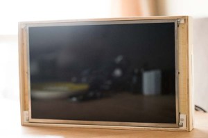
My idea is to make a digital version of the traditional cork table on the kitchen, reading events from Google Calendar, and todo’s from a MongoDB in a node.js app.
To have a cheap display that is able to show a web page on boot, I made a frame of plywood, with a matching plate 1cm from the front to attach the screen of an old laptop. The back-panel plate was cut to size and glued to the frame (leftover glue seen in the pictures).
Nuts on the back of the back-panel secure the screen to the back-panelExtruded PVC is easy to use, durable and strong like wood
To secure the screen to the panel, I used some extruded PVC and cut rectangles that fit between the display and the frame for attaching screws to the display and to the back-panel. Later I will probably paint the box to make it look better. And if I’m going to repeat this project, I will cut 45 deg angles in the corners to make them look smother. With a router I can make nicer edges of the box too.
Found power and groud on the GPIO of the RPi. Boots every time I plug in power in the display adapter
The LCD from an old laptop is powered by a graphics card with many inputs, bought of ebay. A 24 pin flat pack runs through a hole in the back-panel to connect the graphics card to the screen. The data is input with HDMI to the graphics controller, fed from my Raspberry Pi connected to the web wirelessly.
Found a power hub on the graphics controller card where I soldered wires for 5V and ground
I ended up using a Raspberry PI as the brain in the project, as I couldn’t get the Beaglebone to connect to the wireless network (probably need to reinstall the OS on the BBB to make it work, but I gave up in anger). The RPi gets its power from a 5V power hub on the graphics card, I soldered two wires from the graphics card to the input/output pins on the RPi. Luckily, the RPi pulls less amps than the card can supply without rebooting or turning hot. I was planning on installing a voltage regulator (7805) in the setup, but with the available power on the graphics card, this was an easier solution.
The RPi boots to xterm, and loads the webpage I have created in node.js with express, run on an Amazon Web Server with Linux (free and beautiful).
The node server connects to google with oauth2 using passport (NPM), where it reads the google calender I have set up for the family.
Now what’s left is to add a cover on the back, think i will use some thin plastic to cover it all up, to prevent any fingers touching any electricity, and to make a way to hang the frame on the wall.
5cm high, slightly larger than the screen12V power and HDMI used for the projectSeveral inputs that are unused for this projectGlued together for a quick prototype. Improvements: 45 deg cuts, better saw, and some paint to finish
My doors to programming opened up for real as I took a engineering startup course online. It introduced me to Github, Amazon Web Servers, JavaScript, Node.js, Express, Bootstrap, and a world of development for mobile and desktop applications.
I followed a fantastic course on coursera.org named Engineering Startup hosted by Balaji S. Srinivasan, an enthusiastic entrepeneur-turned-teacher out of Stanford University.
By being introduced to basics and quickly setting up a server, a web page and implement some graphics, the bug of coding bit me, and now I spend a lot of time figuring out new features.
I love to learn new technologies, and the feeling of opening up a new toolbox often overshadows the actual need I have, so like many times before, I end up reading and learning how stuff work, diving in to details I probably never will use.
This time I have landed a project where I run a web server on AWS, which reads a google calendar and a MongoDB with to-do actions for the family. Updating of the calendar is done through google’s interface on the web, and I have made a web page for entry and maintenance of to-do actions.
The result is a webpage shown on a screen in our kitchen run by a beaglebone connected to the wireless network. If I only could figure out the wifi-setup on the beaglebone. Might turn to a Raspberry Pi instead if the setup is easier.
The screen is taken from an old laptop, and I’ve made a wooden frame where the computer fits on the backside. eBay provided me with a HDMI screen controller that fits on the back of the screen box.
For power supply I’m using a 12V adapter for the screen, and step down to 5V for the computer with a linear regulator (7605)