

My idea is to make a digital version of the traditional cork table on the kitchen, reading events from Google Calendar, and todo’s from a MongoDB in a node.js app.
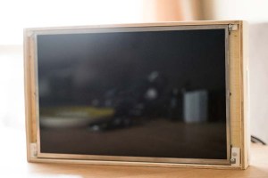
To have a cheap display that is able to show a web page on boot, I made a frame of plywood, with a matching plate 1cm from the front to attach the screen of an old laptop. The back-panel plate was cut to size and glued to the frame (leftover glue seen in the pictures).


To secure the screen to the panel, I used some extruded PVC and cut rectangles that fit between the display and the frame for attaching screws to the display and to the back-panel. Later I will probably paint the box to make it look better. And if I’m going to repeat this project, I will cut 45 deg angles in the corners to make them look smother. With a router I can make nicer edges of the box too.

The LCD from an old laptop is powered by a graphics card with many inputs, bought of ebay. A 24 pin flat pack runs through a hole in the back-panel to connect the graphics card to the screen. The data is input with HDMI to the graphics controller, fed from my Raspberry Pi connected to the web wirelessly.

I ended up using a Raspberry PI as the brain in the project, as I couldn’t get the Beaglebone to connect to the wireless network (probably need to reinstall the OS on the BBB to make it work, but I gave up in anger). The RPi gets its power from a 5V power hub on the graphics card, I soldered two wires from the graphics card to the input/output pins on the RPi. Luckily, the RPi pulls less amps than the card can supply without rebooting or turning hot. I was planning on installing a voltage regulator (7805) in the setup, but with the available power on the graphics card, this was an easier solution.
The RPi boots to xterm, and loads the webpage I have created in node.js with express, run on an Amazon Web Server with Linux (free and beautiful).
The node server connects to google with oauth2 using passport (NPM), where it reads the google calender I have set up for the family.
Now what’s left is to add a cover on the back, think i will use some thin plastic to cover it all up, to prevent any fingers touching any electricity, and to make a way to hang the frame on the wall.


