This article is in a series about making a shelf with lights controlled by an AVR.
Read about
 - designing and building the book-case
 - understanding Mosfets
 - and coding the AVR, and improving it using Atmel Studio
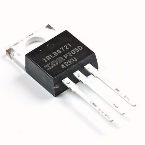
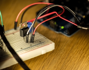
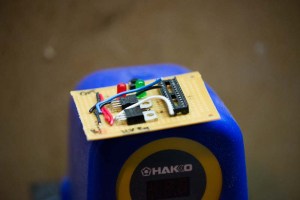
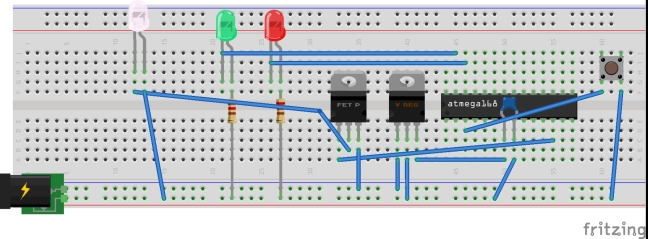
This post shows how I am making the circuit board for a shelf light with an Atmel Atmega168 controlling a Mosfet. And I have come to the point where I let the 240 volt wild wall horse loose on my first Atmega project. Through a 12V AC to DC converter, of course.
It didn’t work.
But I’m very happy to share why. If I wasn’t able to tell you, I wouldn’t be happy at all.
First: wrong reference voltage on MOSFET
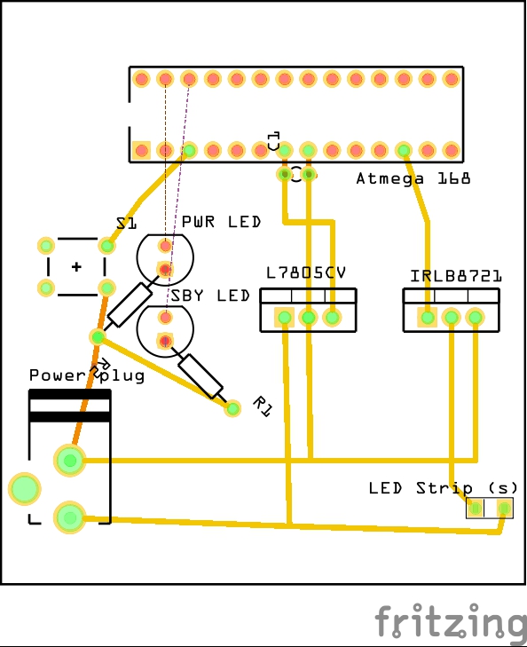
I placed the MOSFET on high side (positive) of the LED strips. That’s a mistake because the gate voltage on the MOSFET is a reference relative to the source, and 5V (full PWM) isn’t much compared to 12V of the flowing current. When I place it after the LED strips (negative), the source is connected to ground, and 5V from the Atmega is much higher than the zero volts of ground. Hence current flows. After fixing this, when I apply voltage through PWM from the Atmega, it has the same zero reference (ground), and the gate opens for current.
Second: wiring it the wrong way
wiring of the MOSFET goes: input to Drain, and output to Source. I did it the other way around.
I hooked up my Arduino to the computer to do some MOSFET testing, it’s very fast to run a program with analogWrite to see if the MOSFET responds to the PWM output. I opened the Fade example sketch in the Arduino software, and just set my own brightness to test with varying light intensity. Even faster testing is to connect the 5V or 3.3V outputs on the Arduino to the MOSFET (ensure common ground).
NOTE: when testing with two power sources, make sure they are grounded together, otherwise, the strangest behaviour from the MOSFET will be seen as voltage is always relative to another point. If the base (ground) is not defined and equal for the two power sources, the behaviour will be spurious.
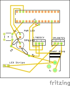
My new PCB now looks like the Fritzing attached, I had to redo some soldering and move some wires to get there, but the initial design was more “there I did it” than “optimimum, optima, optimus”, so I guess that wasn’t too bad after all.
And now the circuit it actually works!
I have purchased several types of LED strips from ebay (all from this dealer), and they come with varying light intensity (power usage) and color.
A LED strip is a 12V section of 3 LED’s and a resistor in series. They light up very brightly, can run a little warm, glue to a surface, and consume less than 200mA for half a meter. They can easily be cut and soldered at every 10 cm, and can be wired together in series.
In my next blog post I’ll share the rest of the code for the Atmega, how I use one button to cycle through power settings.
An advice on resoldering: Use a vacuum de-solder pump. It’s easy to use, and it actually removes excess solder from the PCB. The solder wick you can buy has never helped me anything, it takes long time to heat up the solder through the wick, heating everything else up as well, and it never sucks all the solder you would like to.
